- 您现在的位置:买卖IC网 > Sheet目录1196 > ATAVRMC300 (Atmel)BOARD EVAL LV MOTOR CONTROL PWR
�� �
�
�4.� Hardware� Description�
�This� application� has� been� developed� and� tested� with� ATAVRMC300� and� ATAVRMC310� boards.�
�The� ATAVRMC300� board� is� the� power� board� which� embeds� the� bridge� while� the� ATAVRMC310�
�is� the� processor� board� built� arround� the� ATmega32M1� processor.�
�Refer� to� the� ‘AVR430:� MC300� Hardware� User� Guide’� and� ‘AVR470:� MC310� Harware� User�
�Guide’� in� depth� descriptions� of� these� two� boards.� The� schematics� are� also� available� with� these�
�application� notes.�
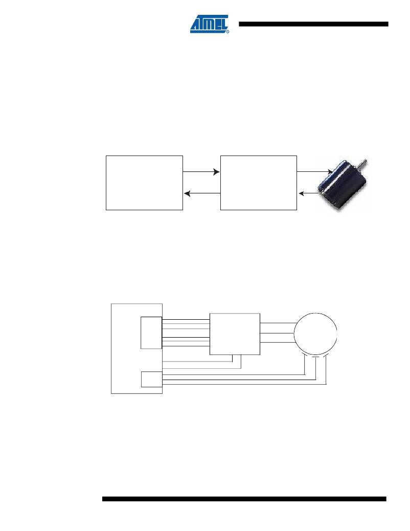
�Figure� 4-1.gives� a� block� diagram� of� the� ATAVRMC310� used� with� an� ATAVRMC300� board.�
�Figure� 4-1.�
�ATAVRMC310� &� ATAVRMC300� connection�
�ATAVRMC310�
�Processor� Board�
�(ATmega32M1)�
�ATAVRMC300�
�Power� Board�
�(bridge)�
�As� shown� in� Figure� 6� the� microcontroller� contains� a� Power� Stage� Controller� (PSC).� The� PSC�
�can� be� seen� as� a� Pulse� Width� Modulator� with� six� output� signals.� To� avoid� cross� conduction� a�
�Dead� Time� control� is� integrated� (see� ATmega32M1� datasheet� for� more� information� about� PSC�
�or� Figure� 8� below).�
�A� fault� input� (Over_Current)� is� linked� to� PSCIN.� This� fault� input� enables� the� microcontroller� to�
�disable� all� PSC� outputs.�
�Figure� 6.� Hardware� implementation�
�ATmega32M1�
�PSC�
�PSCOUT0A�
�PSCOUT0B�
�PSCOUT0C�
�PSCOUT1A�
�PSCOUT1B�
�PSCOUT1C�
�Power� Bridge�
�+�
�Shunt� resistor�
�PH_A�
�PH_B�
�PH_C�
�Motor�
�PSCIN0�
�Over_Current�
�AMP1+;AMP1-�
�ACMP0�
�ACMP1�
�ACMP2�
�Current�
�HallA�
�HallB�
�HallC�
�PSC� :� Power� Stage� Controller�
�ACMPi� :� Analog� Comparator� Positive� input� (i� =� 0,1,2)�
�AMPi+/-� :� Analog� Differential� Amplified� channel� Positive/Negative� inputs� (i� =� 0,1,2)�
�It’s� possible� to� measure� the� current� with� two� differential� amplified� channels� with� programmable�
�5,� 10,� 20� and� 40� gain� stage.� The� Shunt� resistor� has� to� be� adjusted� to� the� amplifier� conversion�
�range.�
�The� Over_Current� signal� comes� from� an� internal� comparator.� The� comparator’s� reference� can�
�be� adjusted� by� the� internal� DAC.�
�8�
�AVR194�
�8138A–AVR–04/08�
�发布紧急采购,3分钟左右您将得到回复。
相关PDF资料
ATAVRMC303
BOARD EVAL MOTOR CTRL W/XMEGA
ATAVRMC320
KIT EVAL MOTOR CTRL CAN/LIN
ATAVRSB100
SMART BATTERY DEVELOPMENT KIT
ATAVRSB200
KIT EVAL FOR AVR SMART BATTERY
ATAVRSB201
KIT REF FOR AVR SMART BATTERY
ATDH1150USB
ACCY USB CABLE JTAG ISP AT18F
ATDVK90CAN1
KIT DEV FOR AT90CAN128 MCU
ATEVK1104AU
KIT EVAL AT32UC3A3256AU
相关代理商/技术参数
ATAVRMC301
功能描述:开发板和工具包 - AVR Processor Brd w/ TINYx61 RoHS:否 制造商:Arduino 产品:Evaluation Boards 工具用于评估:ATMega32U4 核心:AVR 接口类型:I2C, UART, USB 工作电源电压:6 V to 20 V
ATAVRMC303
功能描述:BOARD EVAL MOTOR CTRL W/XMEGA RoHS:是 类别:编程器,开发系统 >> 评估演示板和套件 系列:AVR® 标准包装:1 系列:- 主要目的:数字电位器 嵌入式:- 已用 IC / 零件:AD5258 主要属性:- 次要属性:- 已供物品:板 相关产品:AD5258BRMZ1-ND - IC POT DGTL I2C1K 64P 10MSOPAD5258BRMZ10-ND - IC POT DGTL I2C 10K 64P 10MSOPAD5258BRMZ100-ND - IC POT DGTL I2C 100K 64P 10MSOPAD5258BRMZ50-ND - IC POT DGTL I2C 50K 64P 10MSOPAD5258BRMZ1-R7-ND - IC POT DGTL I2C 1K 64P 10MSOPAD5258BRMZ10-R7-ND - IC POT DGTL I2C 10K 64P 10MSOPAD5258BRMZ50-R7-ND - IC POT DGTL I2C 50K 64P 10MSOPAD5258BRMZ100-R7-ND - IC POT DGTL I2C 100K 64P 10MSOP
ATAVRMC310
功能描述:开发板和工具包 - AVR Processor Brd w/ MEGA32M1 RoHS:否 制造商:Arduino 产品:Evaluation Boards 工具用于评估:ATMega32U4 核心:AVR 接口类型:I2C, UART, USB 工作电源电压:6 V to 20 V
ATAVRMC320
功能描述:开发板和工具包 - AVR Motor Contrl. Kit for CAN and LIN app. RoHS:否 制造商:Arduino 产品:Evaluation Boards 工具用于评估:ATMega32U4 核心:AVR 接口类型:I2C, UART, USB 工作电源电压:6 V to 20 V
ATAVRMC321
功能描述:开发板和工具包 - AVR Motor Contrl. Kit for low cost app. RoHS:否 制造商:Arduino 产品:Evaluation Boards 工具用于评估:ATMega32U4 核心:AVR 接口类型:I2C, UART, USB 工作电源电压:6 V to 20 V
ATAVRMC323
功能描述:开发板和工具包 - AVR Motor Contrl. Kit CPU Intens Algorithm RoHS:否 制造商:Arduino 产品:Evaluation Boards 工具用于评估:ATMega32U4 核心:AVR 接口类型:I2C, UART, USB 工作电源电压:6 V to 20 V
ATAVR-MICTOR38
功能描述:集管和线壳 Connector 4 nexus trace connect 4 AVR RoHS:否 产品种类:1.0MM Rectangular Connectors 产品类型:Headers - Pin Strip 系列:DF50 触点类型:Pin (Male) 节距:1 mm 位置/触点数量:16 排数:1 安装风格:SMD/SMT 安装角:Right 端接类型:Solder 外壳材料:Liquid Crystal Polymer (LCP) 触点材料:Brass 触点电镀:Gold 制造商:Hirose Connector
ATAVRONEKIT
功能描述:电路内置调试器 Debug and program all AVR32 devices
RoHS:否 制造商:Microchip Technology 产品:In-Circuit Debugger Kits 工具用于评估:PIC MCUs, dsPIC DSCs 用于:07-00024, AC164113 核心:dsPIC, PIC 接口类型:USB 工作电源电压:3 V to 5 V